


Why Use a Battery Cut-Off Switch with Alternator Protection?
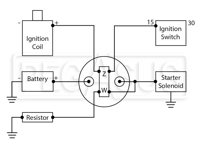
If you disconnect the battery on an alternator-equipped car while the engine is running, the alternator could be damaged by a voltage spike. This spike can be avoided by giving the alternator output a safe path to ground just when the switch is turned off. Our Part No. 4430 Master Battery Switch with Alternator Protection has an auxiliary set of contacts (labeled "W") which are open when the switch is on, but which make contact when the switch is turned off.
A spinning alternator can still put out electricity, so just disconnecting the battery will not stop a running engine. The 4430 switch has a third set of contacts (labeled "Z"), which interrupts the ignition circuit when the switch is turned off.
Wiring the 4430 Kill Switch
- Turn the car off and disconnect the negative battery cable.
- Cut the positive battery cable near where the switch will be located. Install 3/8" ring terminals on each cut end.
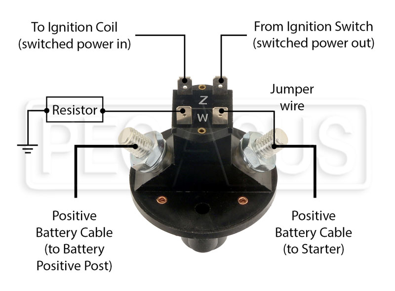
- Connect one ring terminal to one main stud terminal on the switch and connect the other ring terminal to the other stud. Polarity does not matter.
- Locate the main power wire from the ignition switch to the ignition system. Cut this wire and install a 1/4" female spade terminal on each cut end.
- Connect one spade terminal on one of the "Z" contacts and the other spade terminal on the other "Z" contact. Polarity does not matter.
- Now make a simple jumper wire with a 3/8" ring terminal on one end and a 1/4" female spade terminal on the other.
- Connect the female spade terminal to one of the "W" terminals (polarity is not important).
- Connect the ring terminal to the 3/8" main stud terminal which does not lead to the battery. Polarity is important in this step.
If you connect the ring terminal to the stud which does lead to the battery, you will just short the battery to ground, draining the battery and creating a potential fire hazard. - Connect one end of the supplied resistor to the last remaining "W" terminal. Connect the other end of the resistor to a chassis ground. Polarity does not matter.
- Reconnect the negative battery cable.
Test your installation by turning the switch on and starting the car. The battery should charge as normal. With the engine running, turn the switch off. The engine should stop and all circuits should be off.
4430 Master Battery Cut-Off Switch Function Summary
The 4430 switch has three sets of contacts:
- Mains (Normally Open, switch off means circuit is off): These 3/8" stud terminals break contact to isolate the battery when the switch is turned off.
- W (Normally Closed, switch off means circuit is on): These 1/4" spade terminals connect only when the switch is turned off, to provide the alternator output with a safe, loaded path to ground.
- Z (Normally Open, switch off means circuit is off): These 1/4" spade terminals break contact to interrupt power from your ignition switch to the ignition system when the 4430 switch is turned off.
Note that all three sets of contacts are isolated from each other. The power going through the main terminals is not distributed to the ignition system.
Testing the 4430 Master Battery Cut-Off Switch
Testing the 4430 switch usually requires only an ohmmeter or continuity tester, but the switch should be removed from the car and all wiring disconnected before testing.
- Mains: With the switch on, there should be continuity from one 3/8" stud to the other (1.5 Ohms or less resistance). With the switch off, there should be no continuity ("infinite" Ohms resistance). There should be no continuity from either stud to any of the four spade terminals under any conditions.
- W: With the switch on, there should be no continuity from one W terminal to the other ("infinite" Ohms resistance). With the switch off, there should be continuity (1.5 Ohms or less resistance). There should be no continuity from either W terminal to the main studs or to either Z terminal under any conditions.
- Z: With the switch on, there should be continuity from one Z terminal to the other (1.5 Ohms or less resistance). With the switch off, there should be no continuity ("infinite" Ohms resistance). There should be no continuity from either Z terminal to the main studs or to either W terminal under any conditions.
In 99% of cases, those simple tests will verify if a suspected switch needs replacement. If the switch passes all tests but does not function as expected, go back and check your wiring.
Note: This switch should not be used to turn off a running engine except for proof testing and emergencies. Turning off this switch while it is carrying a current of just a few amps will shorten its life. Using a separate ignition switch to turn off the engine and accessories first will allow this switch to reach its full rating of 2000+ cycles.